 |
About AMP Lab Projects Downloads Publications People Links
Robot-based Imaging Test-bed
Team Members
Overview
Background
Expanded System Description
Boid Hardware
Generating a Synthetic View
Planning Group Motion
Contact
|
Brian Stancil |
|
|
Hsiang-Wen Hsieh |
|
|
Tim Murray |
The Robot-based Imaging Test-bed (RIT) is an open source toolkit designed to be used with a network of wireless robots with imaging cameras. The toolkit will provide the infrastructure for wireless networking, overhead camera localization, path planning, path following and image processing. Developers can install various high level applications to use the base classes provided by the toolkit for test purposes. The focus is to construct a robust and well documented system that is easy to manipulate and expand upon while providing a wide range of image processing and distributed robotics capability.
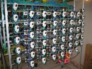
The present system consists of an approximately 2D array of cameras which each independently have 1 degree of translational motion (side-to-side) and 1 degree of rotational motion (pan). The software for this system handles multiple images from each of the cameras and allows the user to create a virtual view point which can be rendered from many angles and positions in addition to the static views of each camera. After observing the target scene, the software determines the optimal configuration of the cameras in the array to minimize error in the rendered view. The cameras can then be translated along the camera array rack to better locations which reduce error in the virtual view.
The new system will consist of small mobile robots (boids) operating on a 2D plane (the arena). Each boid will be equipped with a camera that can be pitched up and down. Localization, consisting of a 2D position and orientation within the arena, will be achieved via an overhead camera and image processing software residing on a base processor. A base process will localize the robots via the overhead images, receive simultaneous images from all robots within the arena and constructs the virtual view, determines an optimal camera configuration based on the 3D model, and coordinate motion between each of the boids in the arena to attain the optimal camera configuration for virtual views. The robots then servo to the new locations and the process begins again by sending the updated images to the base processor.
These boids will provide the tools and infrastructure to test distributed image processing algorithms. Current plans are to produce an initial ten boids for testing purposes, but the system should be expandable to at least 50 simultaneously operating boids.
Applications for this specific type of system include surveillance systems in controlled environments where a centralized “base” process and observation cameras can be provided for localization and the computation of the combined virtual viewpoint. Such systems could include but are not limited to improved building security surveillance and public service surveillance in areas such as bus or train stations and airports.
Ultimately the need for a localizing central process can be alleviated with onboard mechanisms such as GPS, inertial measurement units (IMU), or digital compass hardware. The image processing and world modeling software can also be ported onto the boid platform which will allow for a more distributed system. Systems like this could be deployed in uncontrolled and unsupervised environments for mapping purposes.
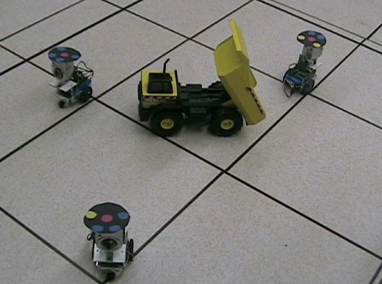
As illustrated in Figure 3, each boid is outfitted with a wireless camera and servos to pan or tilt the camera. The platform for each boid will have two wheels and be capable of point turns and speeds of up to 1 foot per second. The boids will have two wireless interfaces, one primarily for broadcasting images to the base process, and another for accepting motion commands.
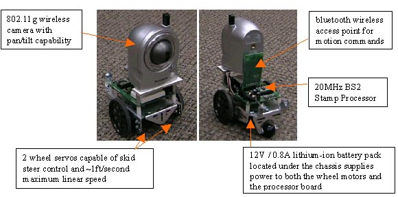
Each of the boid wheel motor servos are capable of delivering 3.4kg-cm of torque. At the present weight, these motors can achieve a straight-line velocity of approximately 1ft/second.
The processor onboard is a 20MHz BS2-IC Stamp processor, which can be programmed using a Parallax IDE using PBasic. In the present configuration, the stamp processor simply reads relative left and right motor throttle percents from the serial port (connected to the Bluetooth transceiver) and translates them into motor speeds.
The algorithm for generating the synthetic view will be similar to the one used in the Self-Reconfigurable Camera Array. However, special care will need to be taken in choosing the neighboring images used for local color consistency verification. Given the mobility of each of the boids, the images could (and often will be) taken from opposing sides of an opaque non-uniform object. For purposes of IBR, images such as these can not be used to produce color correlation metrics. Each of the boids will have the capability to pan and tilt the cameras which is controlled wirelessly via the 802.11g camera interface. The cameras will also provide feedback to the central processor in terms of the angle deviated from center in both pan and tilt. These two values, along with the 2D position and orientation provided by the overhead camera processing software will allow the synthesis algorithm to adequately localize the viewport at which each 2D image is captured.
Figure 4 illustrates the process of recreating a single pixel in a synthetic image from neighboring images via IBR. Theoretically each pixel in all of the boid images should be evaluated over a continuous range of depths to determine the optimal target range at that pixel. However, since this search space is presently too great for real time calculations, the range is discritized and each pixel correlation is measured for this finite set of ranges to determine the optimal target depth in each boid image.
The ability to maneuver anywhere on a 2D plane provides much more flexibility than previous fixed mounted systems. In addition to being able to acquire more views of a given target, this also provides additional opportunities for adjustments to improve synthetic view error. One of the early algorithm development tasks that the CBR testbed will facilitate is the organization and group planning for how each boid can configure itself in space so that the system can optimally cover targets of interest.
 |
 |
 |
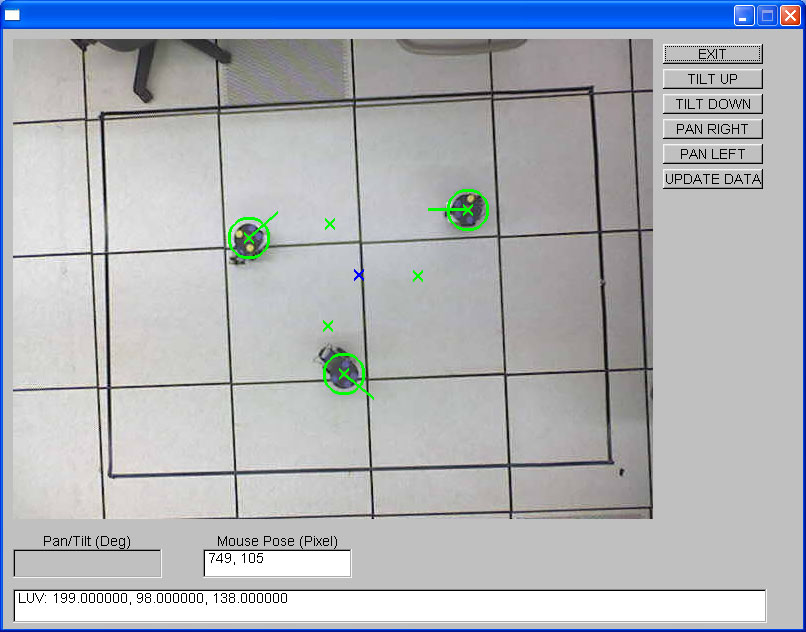
5a |
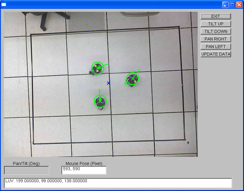
5b |
5c |
In figure 5a, the boids are in their initial position. In figure 5b, a waypoint has been assigned to the boids (indicated in blue). The green markers around the waypoint are final positions for each boid; they are arranged circularly based on the number of available boids. In figure 5c, the boids have moved to their new positions around the waypoint.
Please send any questions or comments to Brian Stancil.